
Do you have questions about our sensors?
Contact our torque sensor and force sensor experts for advice.

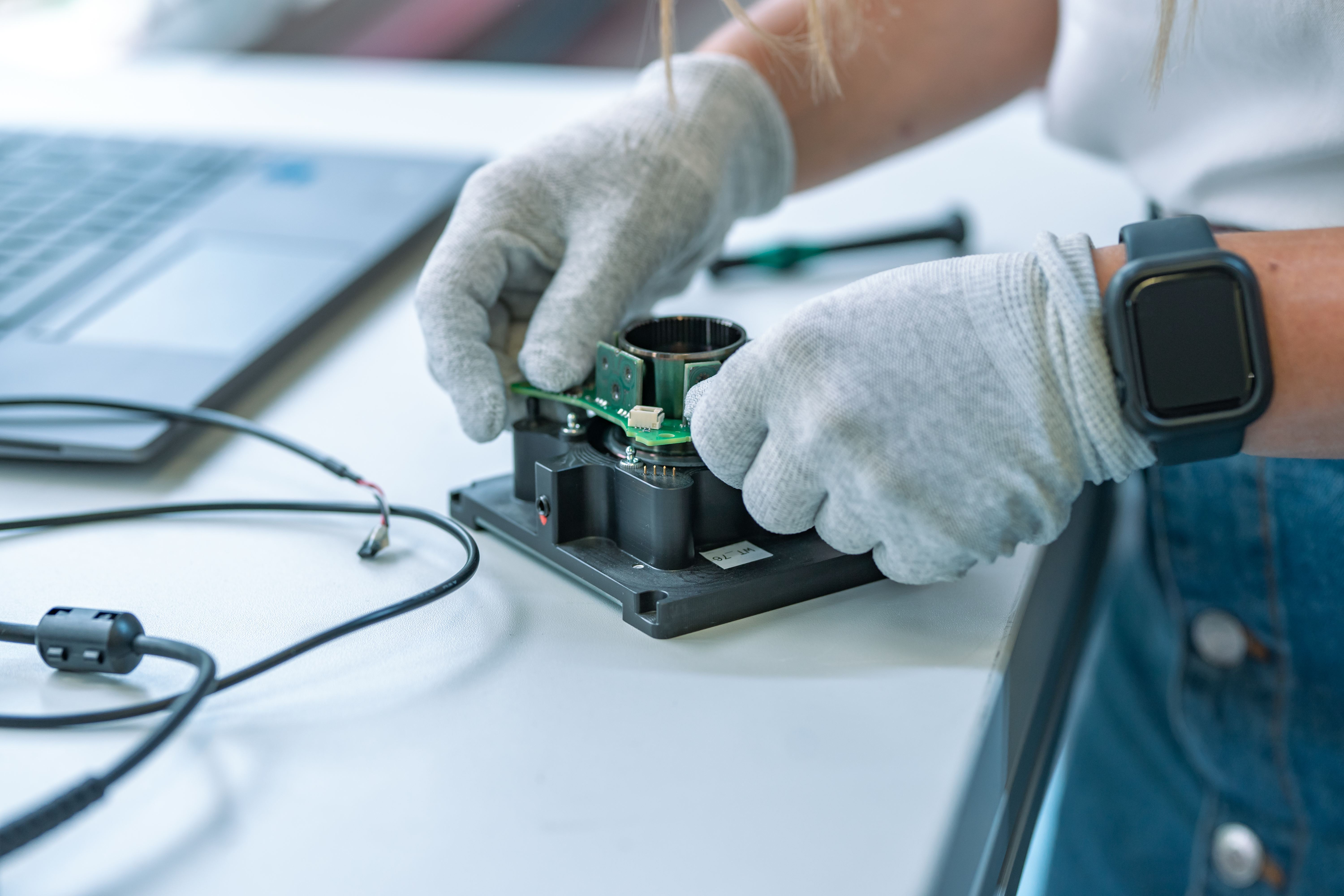
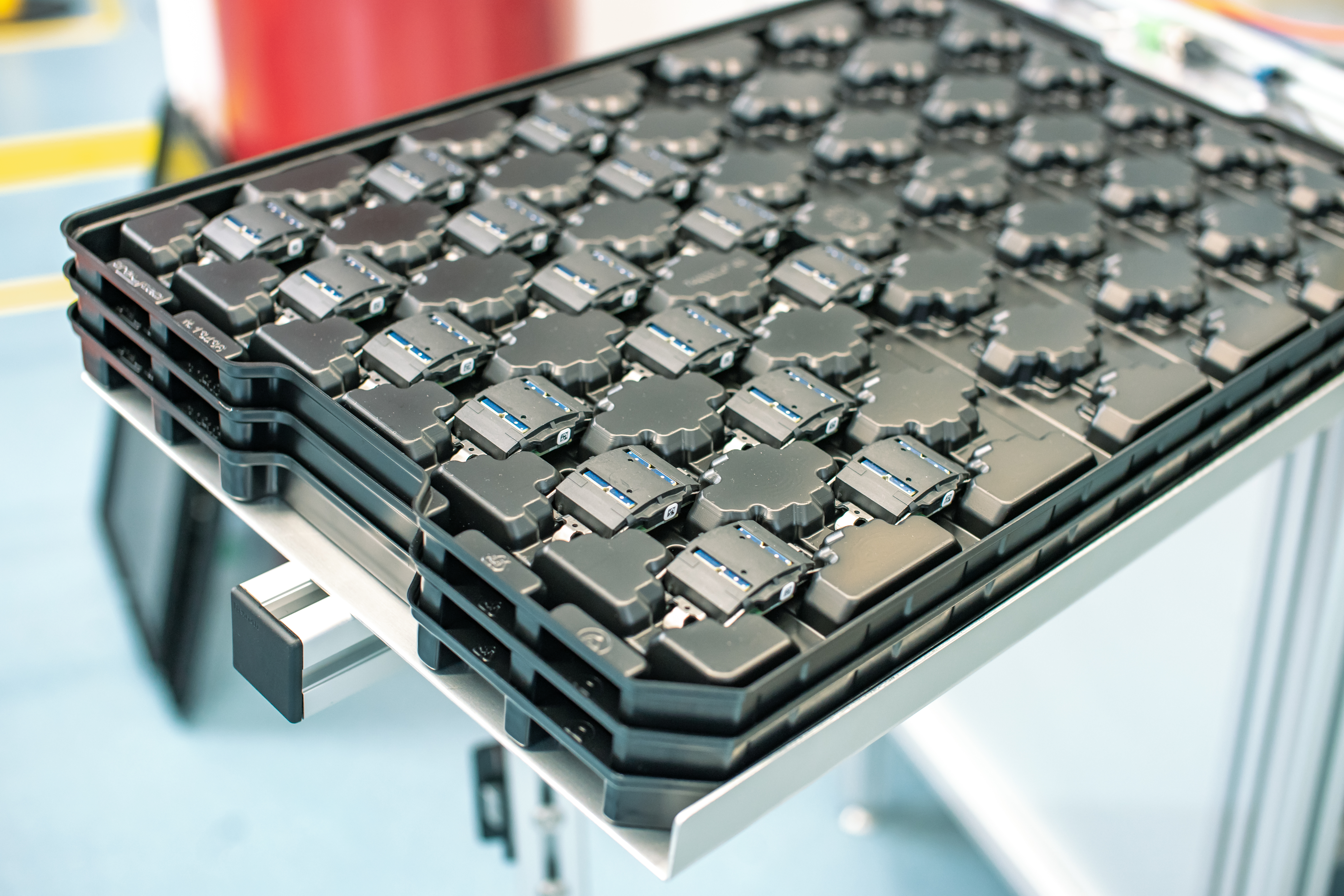
The dimensioning of the sensor depends on the customer's installation space requirements. Various customer requirements can be implemented using a modular system.
Even small dimensions can be implemented in a product through close cooperation with customers.
A direct integration of the sensor into the customer application can also be implemented through a suitable design and dimensioning of the mechanical and electrical interfaces.
The sensor requires a 5V power supply. The current consumption is approx. 100mA at 5V. The output signal for the customer can be designed specifically.
Standard interfaces that are already implemented (SPI, UART, CAN) can be configured customer-specifically.
The standard signal bandwidth of the sensor is 100Hz with a signal-to-noise ratio of < 0.1% FS.
By adjusting the internal signal processing, the output signal can be adjusted to up to 1kHz.
The standard signal bandwidth of the sensor is 100Hz with a signal-to-noise ratio of < 0.1% FS.
By adjusting the internal signal processing, the output signal can be adjusted to up to 1kHz.
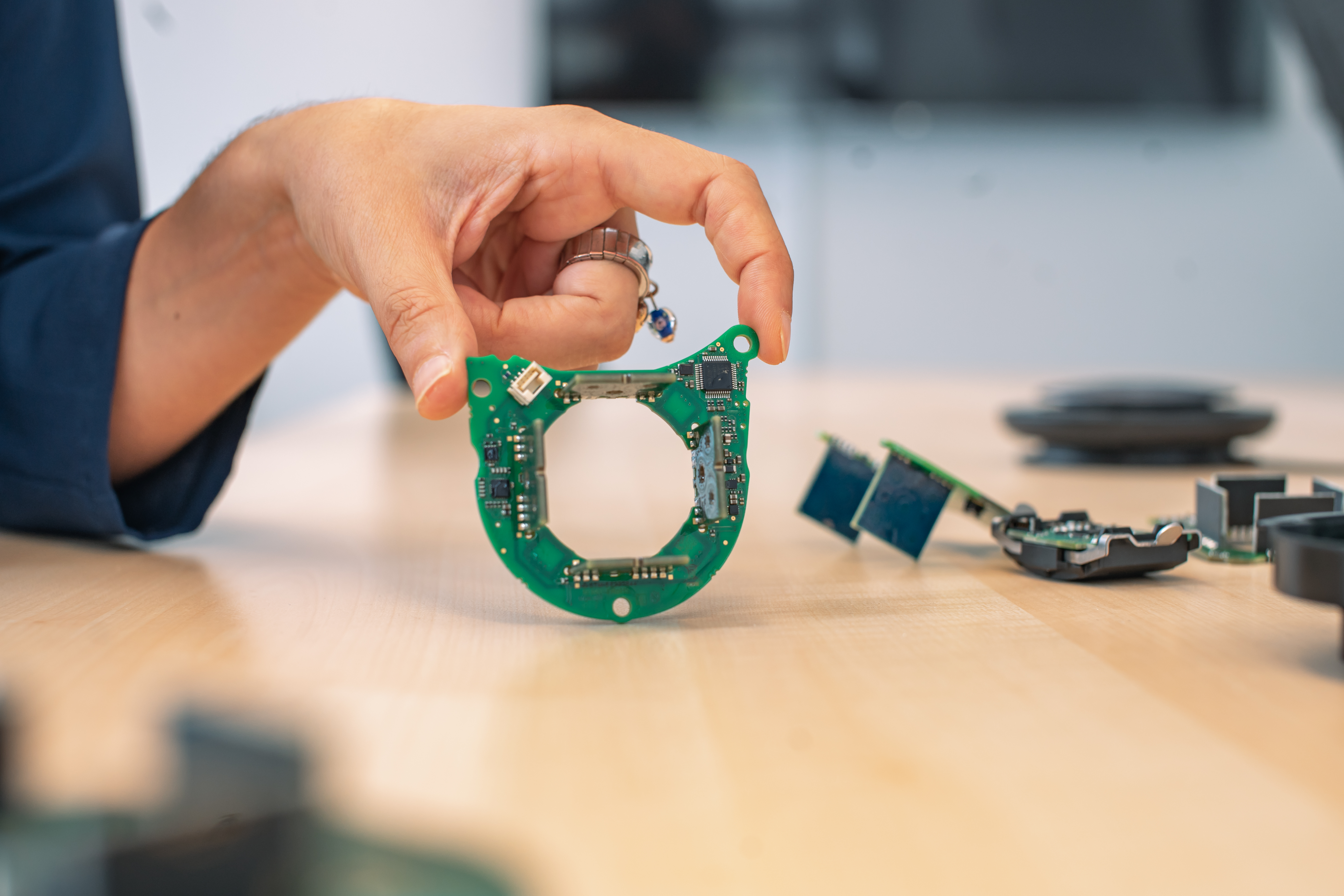
The dimensioning and alignment of the measuring coils defines which mechanical forces are measured.
Customers who have the requirement to measure multiple force vectors, e.g. torque and axial forces, can be served by a customer-specific design and dimensioning of the sensor.
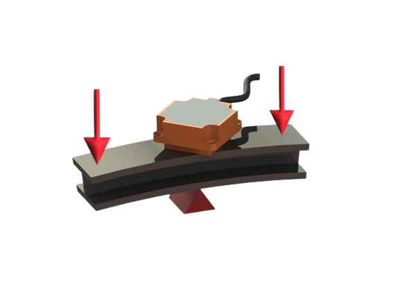
In addition, bending forces can also be determined by evaluating the measurement data. The sensor technology has been developed in such a way that various measuring tasks can be solved by small structural adjustments.
Lorem ipsum dolor sit amet, consetetur sadipscing elitr, sed diam nonumy eirmod tempor invidunt ut labore et dolore magna aliquyam erat, sed diam voluptua.
Lorem ipsum dolor sit amet, consetetur sadipscing elitr, sed diam nonumy eirmod tempor invidunt ut labore et dolore magna aliquyam erat, sed diam voluptua.
Lorem ipsum dolor sit amet, consetetur sadipscing elitr, sed diam nonumy eirmod tempor invidunt ut labore et dolore magna aliquyam erat, sed diam voluptua.
An important prerequisite for the use of the technology is that the measuring shaft is hardened, and it consists of a ferromagnetic material. During initial conversations, we will be able to recommend suitable materials for the waves and the hardenings.
It is important to our customers that the measuring shaft and the sensor are well integrated and that the system is accurately coordinated.
The dimensions of the shaft and the safety factor for overload determine the expected accuracy in the application.


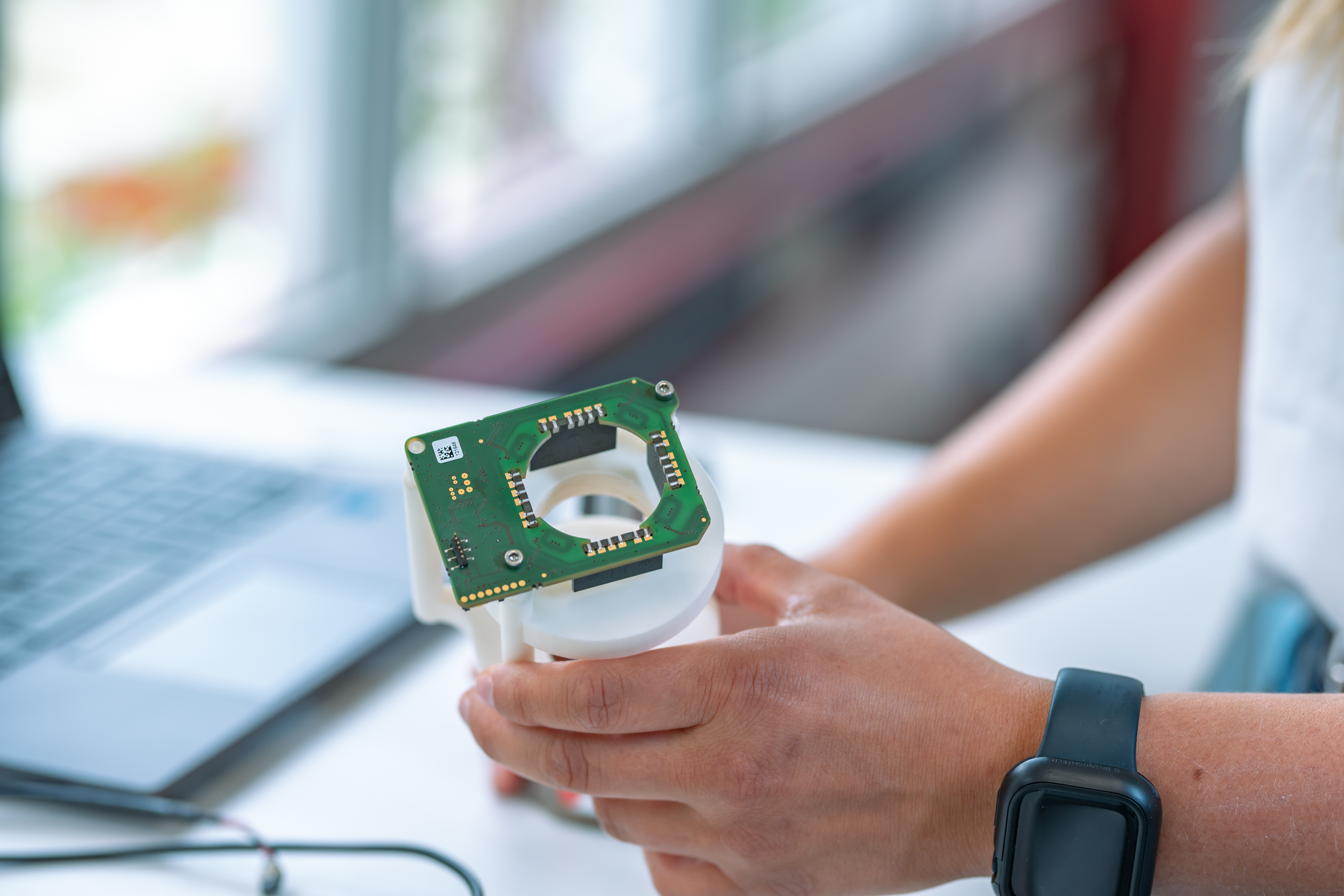
An important factor for accuracy and robustness in the application is the correct dimensioning of the sensor housing and the inclusion of the sensor in the customer application. If possible, the sensor mount must be designed in such a way that the position of the sensor with respect to the measuring point allows for as little movement as possible.
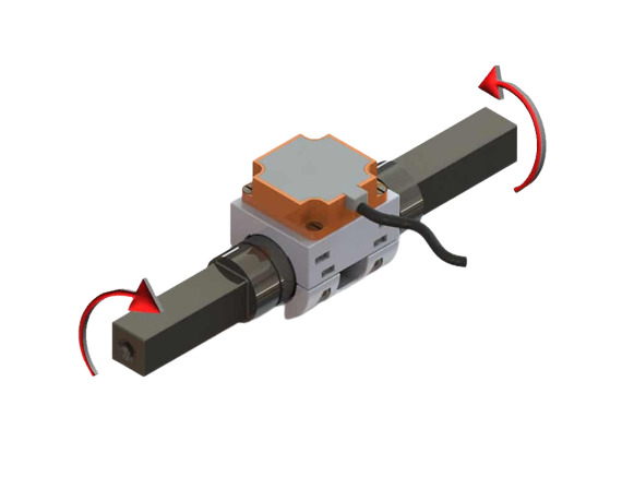
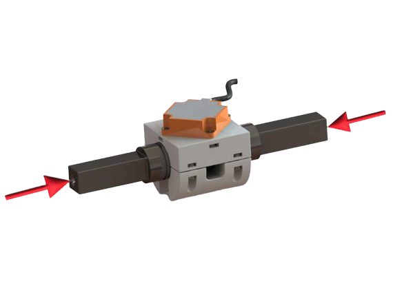
We therefore recommend attaching the sensor as close as possible to a shaft bearing or shaft support. The Active Sensor Module can be placed "inline" to the test object (as with the transmission shaft in the left image) or tangentially in relation to the cross-section of the shaft (right image).
An important factor for accuracy and robustness in the application is the correct dimensioning of the sensor housing and the inclusion of the sensor in the customer application. If possible, the sensor mount must be designed in such a way that the position of the sensor with respect to the measuring point allows for as little movement as possible.
We therefore recommend attaching the sensor as close as possible to a shaft bearing or shaft support. The Active Sensor Module can be placed "inline" to the test object (as with the transmission shaft in the left image) or tangentially in relation to the cross-section of the shaft (right image).
To achieve a reliable torque measurement, the sensor module does not have to touch the test object; the sensor can be up to 1mm from the measuring point.
However, it should be noted that the distance from the sensor to the measuring shaft does have an influence on the measuring accuracy.
The distance between the sensor and the measuring shaft dictates the sensitivity of the overall system. Therefore, the closer the sensor is to the measuring shaft, the greater the signal.
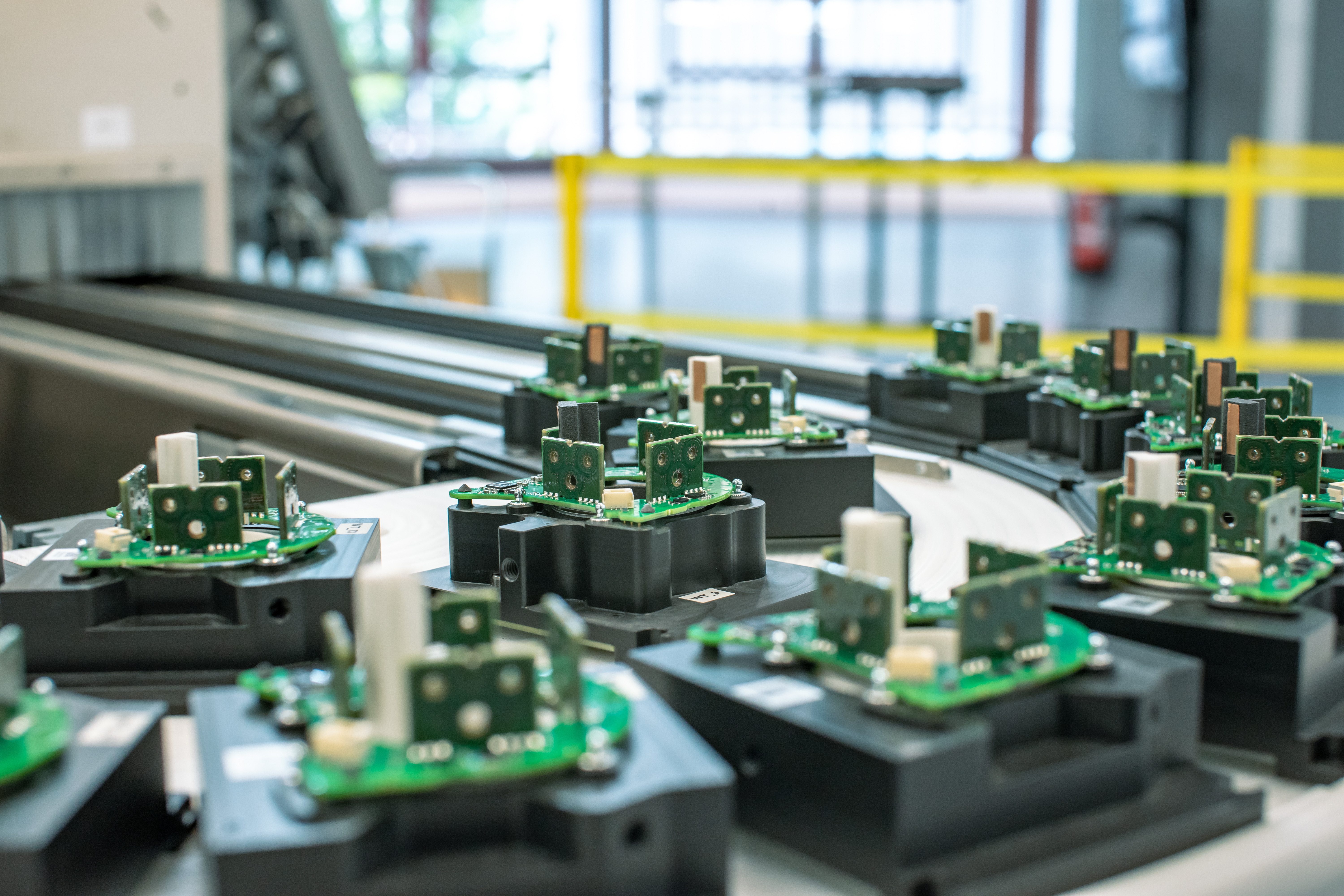
Depending on the measuring task and the requirements for measuring accuracy, multiple sensors can be used.
The use of multiple sensors can gather sufficient information to be able to minimize extraneous measuring effects.
In specific OEM applications, various sensors can also be integrated within one sensor module.
Example of a torque sensor (left) or two torque sensors (right) placed closest to the surface of a rotating shaft (test object).
The torque sensor will sense and measure the selected forces.
Mechanical shock or vibration may affect the sensor signal, so it is important to properly mount and align the sensor.
Appropriate measures in the design of the sensor enable us to recognize and limit the confusion factors during early stages of the development process with the customer.
Proper mounting and positioning of the sensor is essential to achieve accurate measurement results in the application.

The components of the sensor are chosen to meet most industrial requirements from -40 °C to 105 °C.
Alternative components can be used, extending the temperature range to 125 °C.
The components of the sensor are chosen to meet most industrial requirements from -40 °C to 105 °C.
Alternative components can be used, extending the temperature range to 125 °C.
Contact our torque sensor and force sensor experts for advice.